Native KNXnet/IP access
Import the product database and complete group address mapping, programming mode and status feedback in ETS5 — slotting straight into an existing KNX installation.
Turn every circuit in the distribution board into an addressable, measurable, interlock-ready smart node. Native KNXnet/IP, fast ETS5 integration, and coordinated control from web, local panel and cloud platform — simpler, more reliable control of lighting, HVAC, sockets and pumps.
DC12-24V / AC220V power options, specified at order; metering is available on AC models only (suffix M).
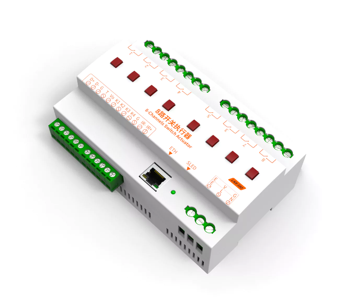
KNX systems, management platforms, PCs and phones can access the same actuator at the same time. Control commands and port status stay in sync in both directions, and local button presses or web operations are reported back to the master in real time.
From protocol access and on-site operation to energy statistics, LNX-6xx pulls the scattered switches, metering and scheduling of a distribution board into a single controllable node.
Import the product database and complete group address mapping, programming mode and status feedback in ETS5 — slotting straight into an existing KNX installation.
Magnetic latching relays hold their current state after switching and keep it on power loss; 20A / 250VAC contact rating suits a wide range of loads.
AC220V models measure voltage, current, active power and accumulated energy on every channel, with field calibration — a solid basis for energy statistics and troubleshooting.
Set several channels to the same address and they switch together as one group — expand switching capacity in parallel with a single command.
Trigger ON, OFF or toggle events weekly, monthly or on a specific date, with second-level accuracy and settings retained through power loss.
An independent button and status LED per channel, so switching is still possible on site when the network is unavailable or not yet configured.
Open the device address in any browser to configure relays, port addresses, metering, schedules, KNX, network and status — no software to install.
Besides KNXnet/IP it also accepts Art-Net event control and UDP ASCII commands, with optional RS485 — easy to hook up to a master controller or platform.
Upgrade firmware remotely over the network as features evolve — no disassembly and no debug cable on site.
Standard RJ45 port; connect to the control network with shielded Cat5e twisted pair — simple wiring and broad compatibility.
A standard DIN rail clip lets it sit inside a control cabinet next to breakers and contactors, keeping maintenance simple.
Set over-voltage, over-current and over-power limits per port address. When a limit is exceeded for the confirmation time, the whole group switches off and locks out — every control entry is blocked from switching back on. Runtime faults recover automatically, cutting site maintenance.
From KNX integration to metering, protection, scheduling and parallel expansion — the five most used scenarios are broken down visually below.
Each relay channel provides two 1-bit group objects: switch and status. After importing the product database, assigning group addresses and downloading in ETS5, the KNX system can control everything by group or by zone, and status changes are reported back automatically.
On AC220V models every relay port can carry metering, showing voltage, current, active power and accumulated energy per channel. The 8-channel model adds four extension measurements C1..C4; on the 12-channel model C1..C4 map to P9..P12 and act as port metering. DC12-24V models have no AC sampling circuit and therefore offer no metering.
Metered models let you set voltage, current and power limits per port address. Ports sharing an address are judged as one address group: voltage uses the highest value in the group, while current and power are summed. When a limit stays exceeded for the confirmation time, the whole group switches off and locks out; during lockout, ON commands from the web UI, panel, schedules, KNX and the master controller are all rejected, so power is never restored into a fault.
Up to 16 schedules can trigger weekly, monthly or on a specific date. At the set time the chosen ports switch on, off or toggle — ideal for opening hours, facade lighting, ventilation and pump cycles.
Set several channels to the same port address and they become one binding group. When the master controller sends a command to that address, the relays in the group switch simultaneously — useful for parallel capacity expansion, higher switching capability, or making several phases of one circuit switch together.
One actuator can serve the KNX system, a network master and local operation at the same time, without conflicts and with live status everywhere.
Import the product database and assign group addresses in ETS5, grouped by floor, zone or function. A natural fit for centralised lighting and power management in hotels, offices and commercial spaces.
Art-Net event control and UDP ASCII commands, plus optional RS485, make it easy to integrate with a LINETX master, a management platform or third-party control systems.
Per-channel buttons and LEDs handle on-site operation; open the device address in a browser to configure and switch remotely — no software required.
Both models share the same control capabilities and configuration workflow; they differ only in output count, default address range and metering channel layout.
| Item | LNX-608 | LNX-612 |
|---|---|---|
| Relay outputs | 8 channels (P1..P8) | 12 channels (P1..P12) |
| Contact rating | 20A / 250VAC | 20A / 250VAC |
| Relay type | Latching | Latching |
| Energy metering | 8 ports + C1..C4 extensionAC220V models only | 12 ports (C1..C4 map to P9..P12)AC220V models only |
| Default port addresses | 101–108 | 101–112 |
| Default KNX group addresses | 1/1/1..1/1/8 · 1/2/1..1/2/8 | 1/1/1..1/1/12 · 1/2/1..1/2/12 |
| Schedules | 16 | 16 |
| Network interface | 1 × 10/100M RJ45 | 1 × 10/100M RJ45 |
| Local operation | Per-channel button + LED | Per-channel button + LED |
| Mounting | DIN rail | DIN rail |
A model number combines “output count + power supply + metering”: the power supply letter is either D (DC12-24V) or A (AC220V); the metering suffix M can only be combined with A, never with D. For example LNX-612AM means 12 outputs, AC220V supply and metering; LNX-612D means DC supply without metering.
| Model | Outputs | Power supply | Energy metering | Typical use |
|---|---|---|---|---|
| LNX-608 · 8-channel series | ||||
| LNX-608D | 8 channels (P1..P8) | DC12-24V | No (not available on DC) | DC power already present, switching only |
| LNX-608A | 8 channels (P1..P8) | AC220V | No (M optional) | AC site, switching only |
| LNX-608AM | 8 channels (P1..P8) | AC220V | U / I / P / E | AC site, per-channel energy statistics |
| LNX-612 · 12-channel series | ||||
| LNX-612D | 12 channels (P1..P12) | DC12-24V | No (not available on DC) | More circuits, DC supply |
| LNX-612A | 12 channels (P1..P12) | AC220V | No (M optional) | More circuits, AC supply |
| LNX-612AM | 12 channels (P1..P12) | AC220V | U / I / P / E | Medium / large cabinets, AC + metering |
About metering: the metering circuit samples through a PT (voltage transformer) and needs an AC supply to work, which is why only AC220V models offer the metering suffix M. DC12-24V models (D) have no metering and a DM combination does not exist; projects that need metering should choose LNX-608AM or LNX-612AM.
When ordering, confirm all three items — channels + power supply + metering (e.g. LNX-608AM). Electrical parameters follow the product nameplate and datasheet.
Standard DIN rail mounting with separated mains and low-voltage routing; relay outputs are dry contacts that can be wired straight into the load circuit.
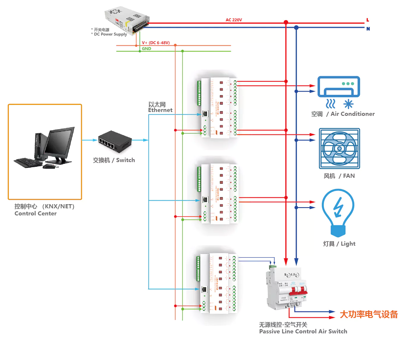 Dry contact output · mains isolated
Whether it is one cabinet of lighting control or power management across floors and zones, LNX-6xx is a dependable execution node.
Control lighting circuits by floor, zone and opening hours, with schedules handling timed switching.
Separate circuit management for meeting-room and open-office lighting and sockets, with one-touch scene changes.
Works with the KNX system for card-key power, lighting scenes and power-off on check-out.
Switch fans, pumps and auxiliary equipment remotely, with metering to monitor running consumption.
Control landscape lighting by sunset time or fixed schedules, with parallel channels driving high-power circuits.
Join the home KNX system to manage lighting, underfloor heating, ventilation and socket circuits together.
Series-wide specifications below; refer to the model comparison or ordering documentation for differences between models.
Operating environment, dielectric strength and dimensions follow the product datasheet and nameplate. Contact LINETX sales and technical support for selection help.
Download the selection guide for full parameters, or read the online handbook and start building your KNX control scheme from the first relay.